Function introduction:
Introduction on its feature and characteristics:
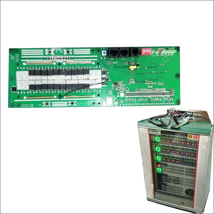
SP16S002 model is a solution specially designed for 16S Lithium ion or lifepo4 type battery pack which can be applicable for different battery with different chemical features :such as for Li ion battery , NCM battery , Lifepo4 Battery etc .it was applied on communication battery system ,portable bases etc
Parameters can be settable via Communication port of the BMS such as voltage ,current etc ,with flexibly application
This BMS will be capable of discharge with constant current of 50A ,BMS can read battery capacity information precisively ,get SOC ,RM,RSOC ,Voltage ,Current ,temperature information of the Battery
BMS leave viarious of communication interface ,RS232/RS485 client can select IT in according to the demand ,communication address can be set via DIP switch on the BMS to fulfil multiple battery communication functions .
BMS can be installed with current limitation module for parallel charge purpose,with 10A limited current .
Except software protection ,we add one more protection of hardware protection to protect your battery fully and enable the application to be more safe and feel more confidently .
Features
- 16 series cell protection
- Full sets of protection for charge and discharge .
- Intelligent balance solution ,the balance current can be adjusted via external components flexibly
- with charge over-current protection function
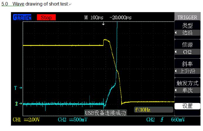
- with hardware protection solution such as Over-current ,short protection
- Enable parallel connection of battery system by choosing the charge current limitation module
- Leave a function of heating at low temperature environment , to perform battery capacity maximally
- With extremely low self-current consumption
- Protection parameters can be adjustable flexibly with support of PC software
- With various alarm function for battery capacity ,temperature ,voltage ,current etc
- With RTC function to record BMS cycle times and abnormity
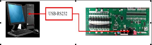
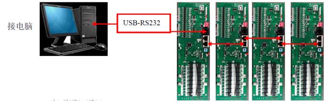
3.7 RS232 Communication solely
BMS can communication with upper host via 232 communication interface ,various of information can be read from the upper host ,communication with computer connection will be as below :
- BMS communicate with upper host via RS232 interface
- Address with BMS can be set flexibly .
3.8 RS485 communication solely :
BMS can communication with upper host via RS485 communication interface , various of battery information can be checked from the upper host , Communication with computer connection will be as below :
- BMS communicating with upper host via RS232 port
- Address can be settable flexibly on the BMS except 0000
- Communication can be normally when select correspond address on host software
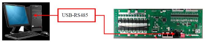
1) BMS communicate with Upper host via RS485 interface
2) Address with the BMS can be settable flexibly except 0000
3) Choose correct address on host via software , then it can communicate normally .
3.9 RS232+RS485 multiple series Communication
While the battery connected in parallels , BMS Communication can be established via RS232 Interface with others BMS , therefore all BMS information can be checked via Host , connection methods as below :
- BMS connected via RS485 interface mutally
- Upper host connected with BMS via RS232
- BMS address set to 0000 which has RS232 communication ,other address set to 0001,0002 etc .
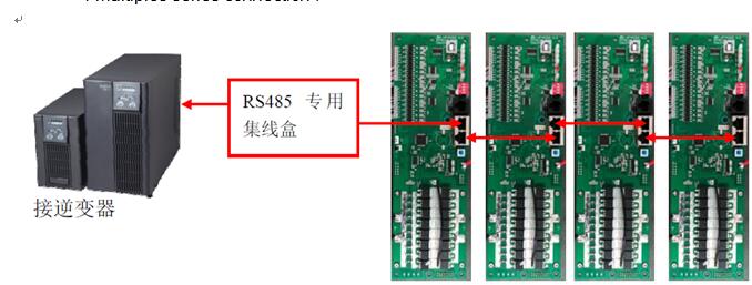
3.10 .Multiple series Communication of RS485 :
While BMS connected in parallels , it can communicate with inverter’s controller with specified hub box ,communication adopted specified communication protocols ,alarm can work on inverter for battery data , support 1 to 4 mode Max .connection method as below .
- BMS communication via RS485 interface mutually
- 485 Hub connected with BMS via RS485 , inverter connected with hub also with RS485 .
Address of connecting BMS must set start from 0x0001,0002,0003 etc , Max support 4 multiples series connection
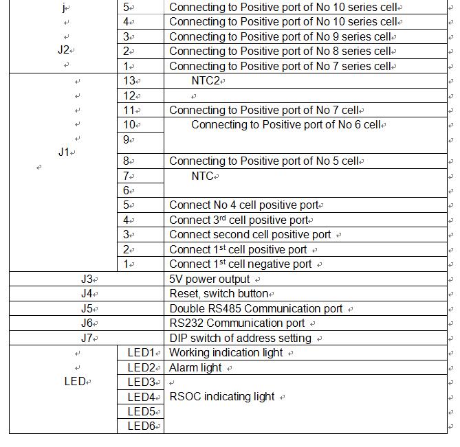
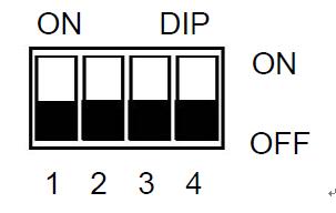
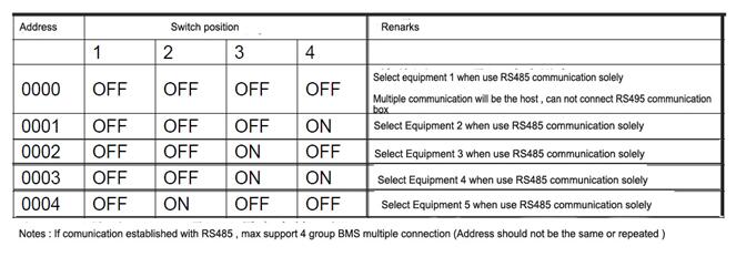
3.11. hardware address switch :
For multiple series communication , BMS should be set with hardware address , and this address can be set via DIP switch on the BMS ,DIP switch definition will be as below :
3.13 Functions instructions :
Overcharge protection: the battery voltage goes up continuously while in the charge process ,BMS will meterthe time immediately when there is any one series of cell with voltage that is higher than over-charge protection value ,bms will turn off the charge Mosfet and charge process will be finished once the time has reached its over-charge protection delay time .
Over-charge protection recovery: when over-charge protection occurred , Battery stays at rest period or battery are in discharge process , battery voltage decreased at such condition . BMS will turn on the charge MOSFET when it detected all of cell’s voltage has got lower than it’s over-charge protection recovery .
Over-discharge protection : Battery voltage drop down continuously in the process of discharge , BMS will turn off discharge MOSFET and discharge can not work once BMS has detected any single cell voltage with lower value than it’s over-discharge protection value and the metered time by BMS has reached it’s over-discharge protection delay time .
Over-discharge protection recovery :
When the over-discharge protection occurred with the BMS , battery stay at rest period or in the discharge status .the Battery voltage goes up continuously . when the BMS has detected every single cell’s voltage which is higher than over-discharge protection recovery voltage , disconnect the load or make charge , BMS will turn on dischare Mosfet , and then battery can discharge .
Over-current protection :When battery stay at rest or in the process of discharge ,battery current increased suddenly . BMS start meter the time once it has detected the current has reach its over-current protection value ,when the time reaches its over-current protection delay time ,BMS will turn off it’s signal and cut-off discharge Mos fet , therefore discharge ca
n not work.
Over-current protection recovery :
When Over-current protection worked , discharge MOS will be turn off , current in circuit get to 0 . while disconnect the load or make charge ,bms start send the signal to turn on discharge Mosfet , then the discharge can work normally .
Charge current limitation:
BMS will start meter the time when it detect the circuit current has reached its over-current protection value ,also working time of constant current in circuit has reached it’s over-current protection time , BMS will send the signal to turn of charge Mosfet , and turn on the charge current limitation module ,the charge current will be limited within 10A . when the battery voltage has been charged to high level , battery will enter into the constant voltage charge phase , charge current will decreased constantly , BMS will turn off charge limitation module automatically when the current reduced to less than 5A , BMS will turn on the charge Mosfet ,and switch to main circuit of charge .